
Upper Quadrant
SEMAPHORE SIGNALS
UPPER QUADRANT
AUTOMATIC SIGNALLING.
It was reported on Page 20 of the W. A. G. R. Annual Report of 1926 that:
“On the 3rd January, 1926, the three position upper left hand quadrant type automatic signalling system was brought into operation in the single line between Bellevue and Mount Helena and on the Down line of the double road between Mount Helena and Chidlow, and the old system of signalling on these roads discontinued.
The new system proved of great assistance in facilitating train operation generally and reducing delays to trains, in consequence of which the working of excessive hours by train crews was, to a large extent, eliminated.
The actual working of the automatic signals during the time they have been in use has been satisfactory, the number of faults for the six months being nine only, or equal to an average of 8,500 signal movements per fault.”
The intention of instituting this form of train working, was to enable a speedier return of the empty grain wagons up hill to the rural areas to enable the shipment of grain from the rich Wheatfields on the Eastern side of Western Australian's Darling Range. Working the trains over the steeply graded line between Bellevue and Chidlow utilising the existing Absolute Block system, using Winter's two-position instruments did not provide the most efficient use of the line's capacity, as only one train was permitted between each pair of the adjoining stations along the route. A way had to be found to reduce these restrictions, and the only way to reduce what is known in the signalling trade as 'headway' (providing a safe distance between trains) was needed. Loaded trains going to the port of Fremantle were not generally a problem as the 'Up' direction trains (those going towards Fremantle), were going down the hill - but 'Down' trains (those going away from Fremantle) were travelling up hill. Even trains of empty grain wagons were difficult to work amongst the other goods services and passenger trains over this taxing line. By the mid 1920s 'turning the trains around' (getting them back to the country) had been recognised as a severe impediment to shipping the state's bountiful grain harvest, and new ways of doing so were constantly being explored. The 3 Aspect Upper Quadrant signals, which were manufactured by the General Railway Signal Company (U. S. A.) seemed to be the perfect answer. These signals were in use by many other railways around the world, and they offered a tried and true control method backed by much reliability. The WAGR did not, however, adopt the 'speed signalling' configuration usually associated with this type of signalling, as used in other Australian states.
The images below explain how the Automatic Signalling - 3 Position worked and shows scans of a Technician's Sketch Book with the track layout and signalling layouts at each of the stations including the extension of the system to Koojedda.
The introduction of this method of train working did not meet with universal acceptance, as is evidenced by one such event, mentioned in the West Australian newspaper reports at the time:
RAILWAY TROUBLES.
GREAT WESTERN EXPRESS DELAYED.
Electric Signal Ignored.
Two Drivers Suspended.
Passengers who left Perth on Thursday evening for the goldfields and Eastern States, were subjected to the annoyance of a three hour delay between Mt. Helena and Chidlow, owing it is said, to the drivers disregarding the regulations relating to the automatic "permissive" block system of signals which was installed recently between Bellevue and Chidlow.
Tuesday, March 16, 1926.
A selection of some of the media articles from the time can be read in the this file: The 1926 Mount Helena Delay
Much discussion was had in the inquest into this delay, and centered around the wording and the interpretation of the Rules and Regulations in force. Eventually, this led to the introduction of a new type of signal - the Absolute Automatic Signal, at which a telephone was provided so that train crews who found themselves at such a signal when it was at the 'STOP' position, could contact Train Control to determine the correct course of action. Outwardly, these signals were virtually the same as their Automatic counterparts, but they had a Red Triangle surrounding the Red Marker Lamp which was in use at the time.
Whilst the Upper Quadrant signals were intended for use in the hills area only, a select few were pressed into service between East Fremantle Goods Junction Box and North Fremantle due to the Fremantle railway bridge being washed away during the great flood of 1926. During the process of rebuilding the double-track bridge, single line working was instituted, initially using Electric Staff Instruments, but in order to increase flexibility and efficiency, the electric signals were brought into use - Pages 910 and 915, of Weekly Notice No 47 of 1926 announced:
FROM THE CHIEF TRAFFIC MANAGER.
North Fremantle - East Fremantle Goods Junction - Installation of Semi-Automatic Signalling. - On Monday, November 22nd, 1926, the working of traffic between North Fremantle and East Fremantle Goods Junction under the Electric Train Staff system will be discontinued and superseded by the Semi-Automatic Signalling system in accordance with Appendix X, Automatic Signalling on Single Lines of Railway, pages 15 - 55.
Change over will be made during the forenoon, and No. 253 Down Passenger train, 11 a.m. Ex Fremantle, will be the first train to travel over the section under the new Signalling System.
Page 910, W. N. 47 / 1926.
ADDITIONS AND AMENDMENTS TO GENERAL APPENDIX.
Pages 261 - 262 :
East Fremantle Goods Junction. - Add to instructions appearing on page 261 :-
Semi-Automatic Signal No. 3, in addition to being controlled by the track circuit, is locked in the normal position when the single line is occupied.
Insulated Sections :
Up Main. - Extending from Junction Points No. 20 to Up Starting Signal No. 25. This section locks signal Lever No. 26.
Up Main. - Extending from Junction Points No. 20 to the fouling point of No. 18 Points. This section locks Signal Lever No. 2.
Page 915, W. N. 47 / 1926.
A chart showing the various types of three position Upper Quadrant Signals as they were introduced over their history is shown below:
1925 |
|
Semi-Automatic Signals (below) - Distinquished by a square-ended RED arm with a White band to the front - Reverse of the arm is a Black band on a White arm. A RED marker light is located directly below the signal lamp. |
|
SEMI-AUTOMATIC Signal at "STOP" This signal can be used as a HOME Signal or a ‘signal controlling the entrance to a section’ of line worked under Automatic Signalling Rules. This type of signal is controlled by the Signalman, and the state of the track to which it applies. Indication: Stop. Section is occupied, or when for any reason, it is required that the train should be stopped. |
|
SEMI-AUTOMATIC Signal at “CAUTION” This signal can be used as a HOME Signal or a ‘signal controlling the entrance to a section’ of line worked under Automatic Signalling Rules. This type of signal is controlled by the Signalman, and the state of the track to which it applies. Indication: Caution. Section is clear to the next signal in advance (the direction of travel), but that next signal is at “Stop.” |
|
SEMI-AUTOMATIC Signal at "CLEAR" This signal can be used as a HOME Signal or a ‘signal controlling the entrance to a section’ of line worked under Automatic Signalling Rules. This type of signal is controlled by the Signalman, and the state of the track to which it applies. Indication: Clear for normal speed. Section is clear to the next signal in advance (the direction of travel), the next signal is at "Caution" or "Clear". |
|
The normal position of a Semi-Automatic signal is at "STOP" |
|
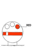
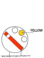
Automatic Signals (below) - Distinquished by a pointed RED arm with a White chevron to the front - Reverse of the arm is a Black chevron on a White arm. A RED marker light is located diagonally below and to the right-hand side of the signal post. |
|
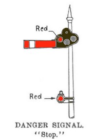
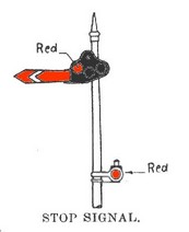
AUTOMATIC (Permissive) Signal at "STOP" This type of signal is controlled by the state of the track to which it applies. Indication: Stop. After the train has been stopped at such signal for one minute, the Train Driver may, if the the line ahead is clear, proceed cautiously, until he receives another Signal for his guidance. |
|
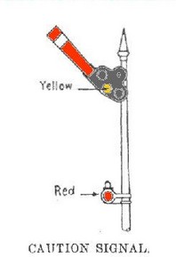
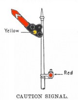
AUTOMATIC (Permissive) Signal at "CAUTION" This type of signal is controlled by the state of the track to which it applies. Indication: "Proceed", next signal is at "Stop". |
|
AUTOMATIC (Permissive) Signal at "CLEAR" This type of signal is controlled by the state of the track to which it applies. Indication: "Proceed". |
|
The normal position of an Automatic signal is at "CLEAR" |
|
1929 |
|
Automatic Signals - Distinquished by a pointed Red arm with a White chevron to the front - Reverse of the arm is a Black chevron on a White arm. A WHITE marker light surrounded by a WHITE triangle is located diagonally below, and to the right of the signal lamp. |
|
AUTOMATIC Signal at “STOP” This signal is placed between stations to divide the section into ‘track sections’. This type of signal is controlled solely by the state of the track to which it applies. Indication: Stop, then proceed in accordance with the regulations. This required that the Driver wait ‘track section time’ – the train’s running time between this signal and the next signal ahead. |
|
AUTOMATIC Signal at “CAUTION” This signal is placed between stations to divide the section into ‘track sections’. This type of signal is controlled solely by the state of the track to which it applies. Indication: Proceed, with caution as the next signal is at “Stop.” |
|
AUTOMATIC Signal at “CLEAR” This signal is placed between stations to divide the section into ‘track sections’. This type of signal is controlled solely by the state of the track to which it applies. Indication: Proceed the track section is clear to the next signal in advance, and that next signal is at either “Caution” or “Clear”. |
|
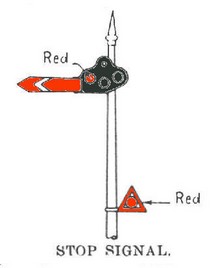
Absolute Automatic Signals (below) - Distinquished by a pointed Red arm with a White chevron to the front - Reverse of the arm is a Black chevron on a White arm. A RED marker light surrounded by a RED triangle is located diagonally below, and to the right of the signal lamp. |
|
ABSOLUTE AUTOMATIC Signal at “STOP” This signal is placed between stations to divide the section into ‘track sections’. This type of signal is controlled solely by the state of the track to which it applies. Indication: Stop. The Engine-driver must then immediately communicate with the Train Controller by means of the phone provided on the signal post. The Train Controller will then advise the Engine-driver whether or not the signal may be passed in the |
|
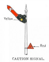
ABSOLUTE AUTOMATIC Signal at “CAUTION” This signal is placed between stations to divide the section into ‘track sections’. This type of signal is controlled solely by the state of the track to which it applies. Indication: Proceed, with caution as the next signal is at “Stop.” |
|
ABSOLUTE AUTOMATIC Signal at “CLEAR” This signal is placed between stations to divide the section into ‘track sections’. This type of signal is controlled solely by the state of the track to which it applies. Indication: Proceed the track section is clear to the next signal in advance, and that next signal is at either “Caution” or “Clear”. |
|
The normal position of an Absolute Automatic signal is at “CLEAR” |
|
1933 |
|
Semi-Automatic Dwarf Signals - Distinquished by a Semaphore Arm, painted on a White target; The target revolves vertically. These signals automatically assume the ‘STOP’ position as soon as a train occupies the line ahead. In some cases Dwarf signals were mounted on poles for ease of sighting. Normally though, they were located at ground level. |
|
SEMI-AUTOMATIC Dwarf Signal at "STOP" Dwarf signals were used to control the shunting movements of trains at stations on sections of line worked under Automatic Signalling (upper quadrant) Rules. This type of signal is controlled by the Signalman, and the state of the track to which it applies.
|
|
SEMI-AUTOMATIC Dwarf Signal at "CAUTION" Dwarf signals were used to control the shunting movements of trains at stations on sections of line worked under Automatic Signalling (upper quadrant) Rules. This type of signal is controlled by the Signalman, and the state of the track to which it applies. Indication: Caution. Section is clear to the next signal in advance, but that next signal is at Stop. |
|
SEMI-AUTOMATIC Dwarf Signal at "CLEAR" Dwarf signals were used to control the shunting movements of trains at stations on sections of line worked under Automatic Signalling (upper quadrant) Rules. This type of signal is controlled by the Signalman, and the state of the track to which it applies. Indication: Clear for normal speed. Section is clear to the next signal in advance, and that next signal is at Caution or Clear. |
|
The normal position of a Dwarf signal is at "STOP" |
|
1940 |
|
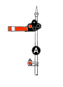
SEMI-AUTOMATIC Signal with 'A' light at "STOP" This signal can be used as a HOME Signal or a ‘signal controlling the entrance to a section’ of line worked under Automatic Signalling Rules. This type of signal is controlled by the Signalman, and the state of the track to which it applies. Indication: Stop. Section is occupied, or when for any reason, it is required that the train should be stopped. |
|
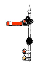
SEMI-AUTOMATIC Signal at "STOP" with 'A' light out and Shunt Signal at "CAUTION" Indication: Stop (Main signal). The Single Aspect Shunting Signal does not authorise movement along the main line of the section ahead, but only applies to a route that diverges from such main line within the Home Signal. |
|
1962 |
|
Rule 64 of the 1962 Book of Rules declared that the Marker lights affixed to Semaphore Automatic and Semi-Automatic signals were coloured Purple, but otherwise retained their positions in relation to the post for each type of these signals. Dwarf signals were not provided with Marker Lights. |
|


All of the W. A. G. R. 3 Position Upper Quadrant signals were rendered obsolete and therefore redundant when the Bellevue to Northam line was closed in 1966. However, these signals, like much of the infrastructure of the line remained in place for many years after. The signals with their colourful glasses became prime targets for those too much time on their hands and too little to do - broken signal lens shards can still be found near the former signal locations - if one is sharp-eyed!
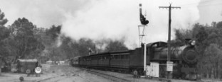
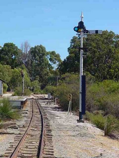
Eventually, the electric signal motors were recovered and once suitably modified, found thier way into service again by the railways for the working of 2 Aspect lower quadrant semaphore signals at various locations around the system. Little, however, remains of this once robust and reliable method of railway signalling. Most of the line through the Darling Range is now a Heritage Railway Walk Trail, and below can be seen some of the signals when in use, and as they are now - remnants of the former signalling system:
To the author's knowledge, two of the Upper Quadrant Signal poles, formerly from the location of Stoneville were re-located to the former Parkerville Amphitheatre grounds for use as Lighting poles. One wonders if there are more around?
More photos of these signals are being sought to hopefully locate the signal bases along the old railway formation (GPS co-ordinates would be welcome), and to completely document this form of signalling through the hills. If you have some information or photos you'd like to share, please e-mail this to: SignallingWA for inclusion on this page.
Information researched and interpreted by Chris. J. E. French of SignallingWA
Coloured graphics by Chris. J. E. French and W. A. G. R. - Photos are as credited in the captions.
This page is copyright, and permission must be sought from SignallingWA before this page is used for any purpose other than personal education.
"Upper Quadrant Signals on the Eastern Railway near Swan View - by Maurice Green"
11/10/2014 - Maurice Green remembers:
"In the cutting just before the Blackboy Hill station (when travelling away from Midland), there was an automatic signal. The approximate location on Google Earth is -31.893,116.048 There was another signal located after the long curve in Greenmount had been traversed and the line was running almost due north. This location was approximately -31.892,116.057 When the train passed the Blackboy Hill signal, it would move to Danger. From our house in Buckingham Road, I used to watch for the train to reach the second location described above and would then see the Blackboy Hill signal move to Caution."
"Upper Quadrant Signals on the Bennett Brook Railway - by Bob Baker"
 Thursday 10th June 2004 - For some time it had been a desire of the Signals Dept of the Bennett Brook Railway (BBR) to have some General Railway Signal Co. (GRS) 3-position Upper Quadrant electric signals operational on the Railway. It was planned to have 2 signals as starter signals at Zamia (formerly known as Maine), approximately midway round the BBR's Bushland Loop.
Upper quadrant signals were in operation on the old eastern railway between Bellevue and Koojedda from circa 1926 until line closure in 1966. The patent for these signals is dated 1918.
As a result of a request for assistance to the Western Australian branch of Australian Railways Historical Society, the BBR obtained a long-term loan of 2 spectacle plates, 2 semi-automatic arms and 1 spectacle casting. Westnet Rail donated a complete upper quadrant mast, lamps, enough hardware to assemble a second mast and relay box for the control circuitry. The Signalling Interest Group of W. A. provided a copy of the 1951 GRS handbook for the upper quadrant mechanisms. These were the catalysts for authorisation by the BBR committee to fund the installation of the signals.
The 2 signal motors required were in store at the BBR. The authentic glass convex lenses were obtained from USA, a second spectacle casting was made and signals staff refurbished the motors, manufactured the platforms, assembled the signals, designed and manufactured the control circuits. The finials are unique and impossible to obtain until a neighbour of BBR's signals technician manufactured the finials from timber and fibreglass using old photographs as a guide.
With all the assembly completed, 12 BBR members gathered one weekend, erected both signals and wired them up. There was great jubilation late Sunday afternoon when the signals moved from danger to caution, then clear.
At the time of writing, there are still some adjustments to be made, a final coat of paint and full commissioning tests to be carried out.
When operational, the signals will rest at danger (horizontal). Approach of a train will cause the signal to go to caution (45 degrees) for 15 seconds and then to clear (vertical) until the locomotive passes the signal when it will return to danger. This will allow passengers to observe the full operation of the signals.
The BBR is proud of the results and is pleased to have invested the money and the 900 manhours to preserve these unique examples of WAGR heritage signalling equipment and thanks ARHS WA Division, Westnet Rail and SIGWA for their valuable assistance.
Bob Baker BBR Signals Dept.