Lever Frames - SignallingWA

Go to content

Lever Frames

Equipment

LEVER FRAMES


Photo courtesy of McKenzie & Holland Catalogue

Since the late 1890s the W.A.G.R.'s preferred signalling contractor was McKenzie and Holland.

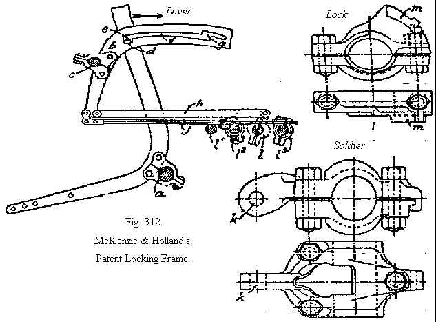
The company's No. 9 Pattern lever frame was selected for use in most of the state's signal boxes and cabins.


The reasons for this choice was, multi-faceted but probably the fact that the robustness of the design, coupled with the fact that virtually no additional machining was necessary to assemble a working lever frame. The frames could be configured and maintained easily by workers with basic mechanical skills, only a few specialized tools and who only required a limited amount of specialised training. Also considered a valuable asset, was that this particular type of frame had what is known as a 4 1/2" pitch. The term 'pitch' being the distance between the centre of one lever to the centre of the next lever in the frame. By way of comparison, the Victorian Railways of Australia also used McKenzie & Holland lever frames, but the pitch of their frames was 5". This may not seem much, being a mere 1/2" more, but when one considers that in the larger signalling installations, which naturally required more levers, this required the building housing them to be much longer, hence more costly. Therefore, the W.A.G.R.'s choice enabled larger capacity of levers within somewhat smaller signal cabins. Whilst it is true that the McKenzie & Holland No. 9 Pattern lever frames formed the bulk of the lever frames in Western Australia, it was not the only type used, this author has found at least one example of a McKenzie & Holland No. 11 Pattern lever frame, complete with interlocking. The pitch of this frame seemed to be about 4", so was even more compact.


Why are lever Frames necessary?
Lever frames were developed to concentrate the control of the signals and points in a station area to provide efficiency in the working of trains. Initially, this meant just the grouping of the levers, but very soon, engineers developed the way of inter-locking for the levers to provide increased safety to the travelling public and staff alike.

A Description of the basic lever frame construction.

The components of the frames were very simple and basic. Using a typical 10 lever frame as an example - this would comprise of an iron casting at each end, between each of these two ends two bearing shafts were fitted, each shafts having been machined for the later fitting of levers at the correct (4 1/2") spacing for this No 9 pattern of frame. Finally, two lenghts of angle iron were attached to the top of the frame castings onto which the required number of floor plates would be bolted between the levers. A Left hand and Right hand end floor plate completed the leverframe in the operating floor area.


How the lever frame worked - 'Cam and Soldier'
The style of locking adopted on this machine is “lever” locking, and the levers are 4 1/2" apart. Fig. 312 shows the lower part of a signal lever, and details of the “soldier” and the lock.

Running the entire length of the locking frame is shaft a, onto which the required number of levers to be used in the frame are secured. Each lever has it's own cam b, carried on another shaft c. On the side of the lever, a stud d is fitted, which projects into a slot in cam b. When the lever is moved from the normal position towards the reverse position, the stud moves to the right, and so forces the right-hand end of the cam down and permits the stud itself to move out of the notch e, into the slot f, and with the continuing lever movement, runs along the slot until it enters the notch g, this gives the cam a further downward movement which secures and positions the stud for the normalising movement.

On the cam being initially depressed, a right to left movement is given to the link h, and the rod j. The link h, is attached at k, to what is technically known as a “soldier” working on a shaft l. Each lever has a “soldier” and a shaft to itself (the shafts l1, l2, and l3 belong to other levers).

On the shaft l, are attached in a line with the levers to be locked or released, locks as illustrated. In the rod j, (called a “T” Iron) notches are cut, into which fit the projection m, on the lock.
Directly the cam b, is depressed by the stud d, the link h, is moved sufficiently to cause the projection m, to enter the notches of those levers to be locked. But should the lever to be locked be already over, its notch would be out of line and the projection m, could not enter, and therefore the lock could not turn nor the “soldier,” and so the parts go on in turn and the lever itself cannot be moved.

In the case of a lever having to release another, then the lever to be freed has the projection m, already in its notch, and it is gradually being withdrawn as the releasing lever is being pulled over, but not until the lever has completed its travel and the stud d, enters the notch g, and so gives the final movement to the cam, link, “soldier” and lock, is the projection m, fully withdrawn, and then directly the freed lever is moved the notch is taken away, the projection cannot re-enter, and so the releasing lever is “back-locked” until the freed lever is restored.

All of the above basic operating description, details the working of the lever frame machine below the operating room floor, and therefore out of sight of the signalman. Depending on the complexity of the the control area of the signal box and therefore the number of levers required, the brackets attached to the rear of the lever frame castings carried many shafts, and for the very complex interlockings, were on two tiers. This required the us of 'top-tier' and 'bottom-tier' soldiers. For instance, the numbers of shafts (shown as l in Fig . 312) could be considerable.

In the W.A.G.R. Drawing E. & S. F74 of the 13th of November 1926, a table sets out the lengths of T Irons j and Links h for both top and bottom tiers, and shows that the maximum potential was 22 shafts on each tier.

The normal W. A. G. R. practice was to use the bottom tier, and when there is no room in the bottom tier, then the top tier was added. Locks are installed on the right and releases on the left in the bottom tier, and vice versa in the top tier, except in special circumstances. W. A. G. R. drawing ES-F-447 refers.

By design, the lever frames were relatively simple machines, but the interlocking of the levers could be quite complex, and utilized the mechanical equivalent of what computer programmers of today know as 'logic gates'. In effect, lever frames were extremely heavy, metal computers, designed and built with the sole intent of preventing accidents, and thereby preventing injury to, or loss of, human life as they travelled by rail. In addition to the concepts of 'lock' and 'release' of the levers to prevent inappropriate lever movements (to afford safety), the frame design could (and did in necessary instances) use gravity, by means of weighted locks or releases, in effect providing the interlocking engineer to 'lock if' or 'release if', etc., this was known as 'special locking'.


Include here a simple example of a simple interlocking chart. The image will show in a new window:

How to interpret an interlocking diagram:
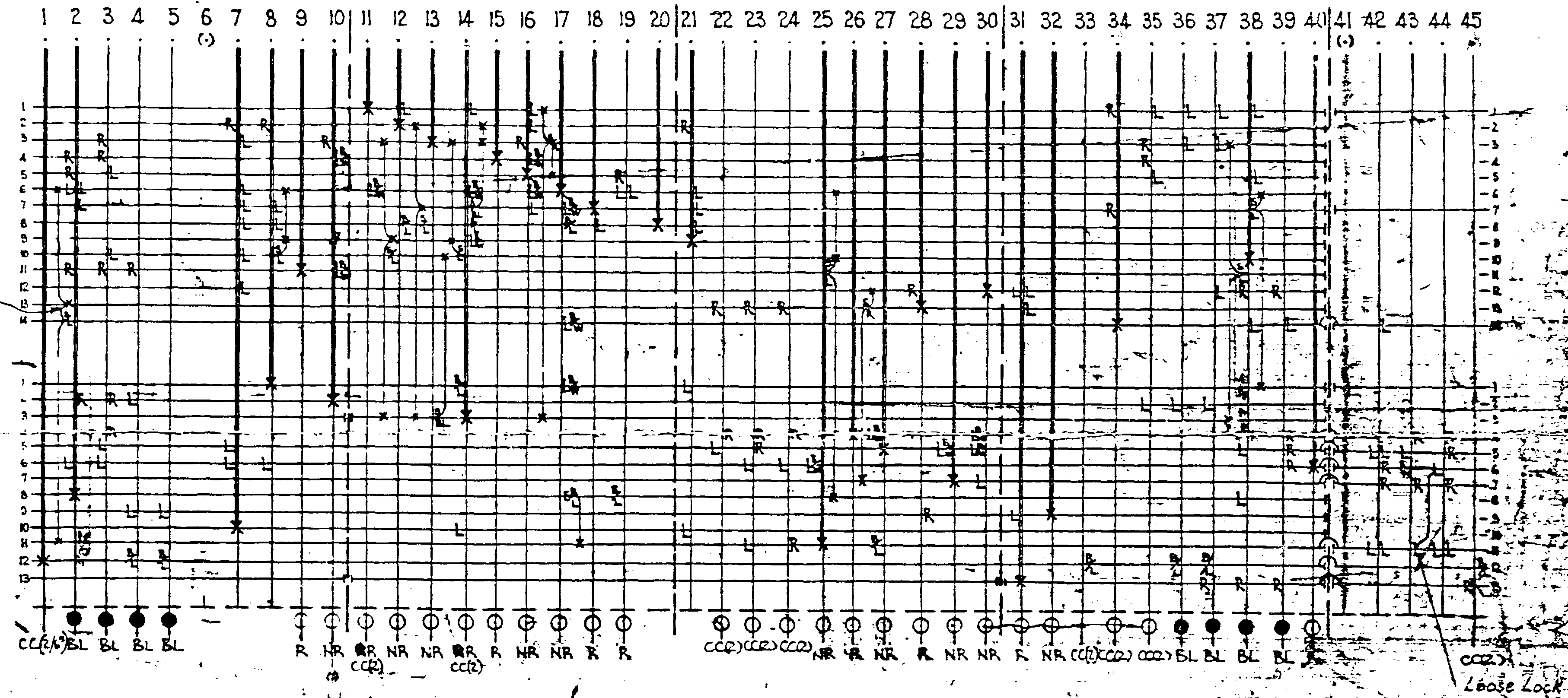
  • The numbers are the lever numbers as seen in the lever frame with the levers (shown as Black circles) all shown in their normal position. Lever No. 7 does not control any equipment as it has no symbols below and is indicated as such by being enclosed within brackets. This would be indicated to the Signalman by the lever being painted white. Spare levers were typically bolted in the normal position to prevent them from being moved. Lever No. 8 is not provided, which is indicated by the brackets being empty. This is what was known as a Space in the line of levers;
  • The verticle lines from and below each lever (No. 8 excepted), represent the T-Irons;
  • The horizontal lines represent the interlocking shafts (known as rocking shafts due to the fact that they do not completely rotate). The number of these shafts depend on the number of levers and the amount of interlocking being provided.
  • The 'X' at the intersection of a T-Iron and a Shaft, represents the location of a 'Soldier'. By way of example, with all levers being normal (being away from the Signalman). When looking at the chart, 'Soldiers' can be seen as located on levers Nos. 1, 2, 5 and 6. By way of explanation, lever No. 6, when pulled over to 'Reverse' (being near the Signalman), will cause the partial rotation of the first shaft in the interlocking tray.
  • The 'R' symbols indicate (somewhat confusingly) the location of a lock which has been fitted to the rocking shaft and positioned so that it engages into the notch of the T-Iron to prevent that lever's movement. As the first shaft has two 'R' symbols along it's length (on levers No. 1 and 2), the partial rotation of this shaft, will then remove the locks from the notches and therefore 'Release' that lock on Levers No. 1 and 2 at the same time. Both levers 1 and 2 will still be prevented from movement however, as lever No. 5 will also have to be pulled in the same fashion as before to dis-engage the locks completely - this is done by Lever No. 5 'Releasing' the locks on the second shaft in the interlocking tray.
  • With both lever Nos. 5 and 6 having been moved to the reverse position, they have both partially rotated the shafts by means of the Soldiers fitted to shafts 3 and 4 in the interlocking tray and engaged the locks positioned on those shafts further along the tray, the action causing the interlocking of levers 3, 4, 5 and 6.
  • In order to return the levers to their normal position, one has to return them in opposite order of pull.
  • This form of interlocking of levers provides essential safety and as the reader might gather from this simple example, signal cabins with a large numbers of levers had very complex interlocking charts.

Sykes Lock and Block Controls.

The design of the McKenzie and Holland lever frame proved to be very adaptable to emerging railway signalling control technology. Such was the case when Sykes Lock and Block instruments were introduced in the early 1900's. For the first time on the WAGR system, Signalmen were prevented from placing starting signals to proceed until it was electrically released by the Signalman in the next signal cabin ahead, or in railway parlance 'in advance'. This was achieved by the connection of steel control rods from the instrument to the signal levers below floor level.


Application of Electro-Mechanical Interlocking.

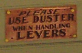
The design also permitted the easy addition of electro-mechanical control, such as Gravity Locks which were introduced around 1911. These were an electric coil fitted above the back end of a 'T-Iron' which, when permitted to do so by the electrical interlocking, removed a metal lock from a specially cut notch in the 'T-Iron', thus allowing it to be moved. These items were typically used for simple track occupancy locking situations, meaning that should a track be occupied by a railway vehicle, then the lever controlling the points would be prevented from being moved. When first introduced, the electrical supply to these locks was controlled by two floorplate switches worked by the action of the catch handle rod at the rear of each lever - one switch was in the normal position and another in the reverse position of the levers between the levers in the Operating Floor area. These switches were still being used in many signal cabins until the end of their working lives. In practice, the floorplate switches in particular attracted the lint from the yellow dusters used by the Signalmen when working the levers and they were difficult to keep free of dust and dirt. Later, some signal cabins were provided a single steel foot button in line with the lever to be worked. In England, these floorplate switches or foot buttons were referred to as 'economisers'. When either of these types of switches were activated, and provided the track circuit was clear, the operator could hear the Gravity Lock 'pick' (engage) and therefore release the lever for movement.  


Colour Light Signalling Modifications.
With the introduction of Colour Light Automatic Signalling on the Perth Metropolitan lines, and even some regional installations, the signals controlling the colour light signals were fitted with Force Drop Lever Locks and Circuit Controllers. Along with the change in the field from mechanical semaphore signals to colour light signals, the effort required on the part of the Signalman to move such levers was reduced significantly. Whilst there was a policy to indicate this change to the Signalman by cutting a section off the top of the lever affected handles to visually indicate that less effort was required, this policy seemed to have been short lived and was not universally applied to all lever frames.


Tappet Locking adaptations.
Further examples of alterations could be found at Rivervale and Kwinana signal cabins were the system of Tappet Interlocking was used. Kwinana in particular, had both Cam and Soldier (rocking shafts) and Tappet Locking as well. Tappet Locking was widely used in England, and being very compact, could achieve - as in the Kwinana case, an extension of the interlocking function without the need for an increase of the infrastructure.  

Colours of levers.
The painting scheme for the levers in WAGR signal Cabins were similar to most railway which adhered to English signalling practice, a exception being the use of YELLOW levers:
COLOUR
USE
NOTES
REDSignalsAll Signal types including mechanical Distant Signals
BLACKPointsWorking trackwork points and / or crossings
BLUEFacing Point Locks and / or BarEngages a locking device at the trackside of the above
BLACK and BLUEPoints and Facing Point Lock combinedWhere a single lever is configured to control the functions of Blue and Black levers simultaneously
YELLOWPermission LeversUsed for releasing trackside switchlocks or other remote lever frames
BROWNBolt LocksA mechanical control of an external item of equipment
GREENAutomatic Control Cut-Out LeversSometimes known as a 'Switch-In' / 'Switch-Out' or 'King' Lever
WHITESpareLevers which are not currently in use
Continuing with the exceptions, the WAGR adopted the practice of painting the 'Lead Numbers' on the sides of the levers, unlike the English policy of detailing these on cast plates fitted on the front of the levers concerned.

These 'Lead Numbers' are, in reality, the 'Releasing Numbers' for a lever. Which is to say that they are the numbers of the levers needed to be pulled over before the lever displaying those numbers is free to be used.

Generally speaking, the lead numbers are painted on the side of the lever nearest to the centre of the leverframe, so that they can be read with ease by the operator as they approach the lever.

Every attempt was made to have these lead / releasing number sets follow the principal of - Using a 40 lever lever frame as an example and from the mid-way point along a lever frame:
  • Levers 1 to 20 - Releasing numbers painted on the Right Hand Side of the levers with the release numbers being from Highest to Lowest
  • Levers 21 to 40 - Releasing numbers painted on the Left Hand Side of the levers with the release numbers being from Lowest to Highest
The above was the model of how it was supposed to be done, but as always, the layout of tracks at different stations and the difference in the resulting interlocking plan meant that it was not always possible to have these sets of numbers (lever-pulls) occur in straight numerical order. Signalmen referred to these releasing numbers as 'sequences' and they soon memorised all of these very quickly.

A Signalman's responsibility in regards to levers
Signalmen were generally, required to keep their workplace and equipment well cleaned. This was to be carried out during non-busy times, and included polishing the brass name plates, sweeping the floor and polishing same as well as keeping the windows clean and of course ensuring the lever handles were meticulously clean and devoid of rust. Of course in very busy boxes and cabins, and particularly when a Block Boy was employed, this domestic work was to be carried out by him. The correct method of cleaning the lever handles was explained to the Block Boy, and many a boy was chastised if he should get it wrong! The top portion of the lever, known as the handle - with the catch-handle behind same, was to be kept brightly polished at all times. There is a common misconception that the lever handles were brass. This is not so, as the lever handles were forged from the same material as the rest of the lever. The cleaning of lever handles was seen as a matter of pride in the workplace and it was a constant battle against the natural moisture in the air and occasional mishandling of the Signalman's lever duster.
  • The first task to maintain the lever and catch-handles was to remove any trace of rust. This was done by a light touch with a fine grit wet and dry or fine sandpaper - the most important part if this procedure was to NEVER use the paper in circular motion around the levers as this left scratches in the steel which were hard to erase. The correct method, was that they had to be cleaned 'along the grain' of the steel - this term meaning that they had to be cleaned in an upward and downward manner. and polishing lever handles.
  • The second task was to remove any trace of the rust remains with a cloth - NOT a lever duster, as any rough patches could 'catch' on the duster fabric.
  • The third task was to use a burnisher to completely polish the steel. Burnishers were nothing more than a square piece of leather with metal rings attached to the edges which covered one entire surface -yes, it what was once known in olden days as 'chain mail' as used by medieval knights. The burnishing also had to be done 'along the grain' of the levers, and when completed, the result was a highly polished steel surface that not only shone like a mirror, but one could also read the reflection of a page of a book from its surface.
  • Finally, a quick wipe-over with another cloth would ensure that no metal residue remained.
In a cabin with a small number of levers, this work would not take too long, but in the bigger cabins the work seemed to be a never-ending task. Is it any wonder why there were signs in some cabins such as this - for neither a Signalman nor Block Boy wanted all their hard work spoiled. Towards the end of the traditional lever-operated Signal cabin era when signal cabins were not manned daily, the painting of lever handles was carried out. This was similar to the painting of lever handles of outdoor, or 'Station Frames' but in the cabins the levers were almost always painted silver. This prevented the need for de-rusting and burnishing but the levers just looked plain, dull and uninteresting.

The Signalman's Duster
Using the duster was a skill that required mastering too. The typical WAGR duster was made from a square piece of yellow fabric with rounded corners and an over-locked red cotton hem all around. The correct way to hold it, was to lightly hold two of the adjacent corners of the duster between the index finger and the middle finger of both hands. The trick came in the form of 'forgetting that it was there whilst levers were being worked. When approaching a lever to work it - either way - the signalman would put their dominant hand on the top of the lever (as it is is easier to use a lever the furthest away from the fulcrum as possible) and the other hand is then positioned lower down the lever so as to enable that hand's fingers to reach the catch-handle behind the lever. If this has been done correctly, the duster should have totally deployed onto all of the steel areas of the lever and no skin-on-steel contact will be made. With practice, it becomes second-nature.  

Working the frame - The correct way to use levers
Whilst all levers looked the same as they stood clean and shining in the lever frame, but Signalmen quickly found out that not all levers were the same when worked ('pulled over' - from Normal to Reverse,  or 'put back' - from reverse to normal).

For instance, RED levers controlled signals and when they were in the yard near the signal cabin they might easily be pulled over without much effort - possibly with a single hand, yet Distant signals (also painted RED on the WAGR) and positioned at the farthest distance from the signal cabin, might require the Signalman to use all his effort of two hands, and his entire weight to pull them over in order to give a 'proper' signal to the Driver of a train.
Similarly, Points levers (painted BLACK) - in the case of a Catch-Point (a de-railer), a lever might only move a single point blade, yet a similar BLACK lever next in the frame to it might work up to 4 blades in the case of a cross-over or even more in the case of controlling a 'compound' (double-slip) point which also worked another set of points to form a crossover.

Working the frame certainly had it's challenges, but a good signalman found that by paying attention to the 'feel' of the levers as they were worked, he could tell if a signal might need adjusting due the signal wire becoming slack, or a set of points were becoming 'dry' and required oiling. The state of other equipment could also be determined, for instance when a Facing Point Lock was not engaging to effectively lock a set of points, this usually meant that there may have been an obstruction in the blades of the points or that the lock itself might be damaged. Sadly, all of this tactile feedback was of course lost when the lever signal cabins were replaced by electric control from remote signal panels.
The McKenzie & Holland lever frames used by the W. A. G. R. were so robust, that in many stations in regional areas of Western Australia they were used in the open air, usually situated on station platforms. Examples of these can be seen in the Archive section on the Station Frames page of this site.


If you have some information or photos you'd like to share about this topic, please e-mail to: SignallingWA for inclusion on this page.

Information on this page has been researched and interpreted by Chris. J. E. French of SignallingWA

Graphics of interlocking are from former W. A. G. R. training materials as are original drawings.

Photos are as credited in the captions.

This page is copyright, and permission must be sought from SignallingWA before this page is used for any purpose other than personal education.


Back to content